Alternating Current – Complete Guide For Class 12 Physics Chapter 7
Welcome to iPrep, your Learning Super App. Our learning resources for the chapter, Alternating Current in Physics for Class 12th are designed to ensure that you grasp this concept with clarity and perfection. Whether you’re studying for an upcoming exam or strengthening your concepts, our engaging animated videos, practice questions and notes offer you the best of integrated learning with interesting explanations and examples.
The chapter Alternating Current explores the fundamental concepts that govern the behavior of AC in electrical circuits. It delves into key principles such as the sinusoidal nature of AC, its representation through peak, average, and root mean square (RMS) values, and the comparison with direct current (DC).
The chapter explains the behavior of AC in resistive, inductive, and capacitive circuits, highlighting phase differences between voltage and current. It introduces the concept of impedance and explores resonance in LCR circuits. Additionally, it covers the calculation of power in AC circuits, emphasizing the power factor’s importance. The role of transformers in the efficient transmission of AC over long distances is also discussed.
Understanding Alternating Current
The chapter Alternating Current (AC) explores the fundamental principles governing the generation, behavior, and applications of alternating current, the type of electric current that powers most modern electrical devices.
AC Fundamentals
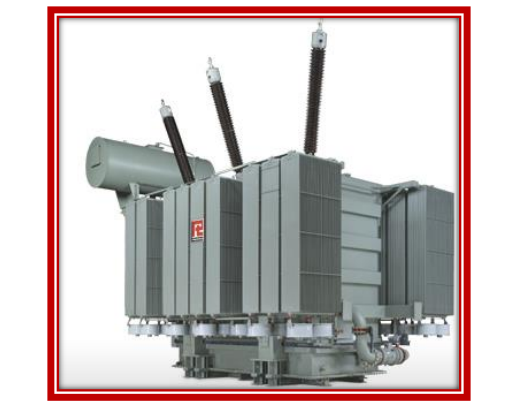
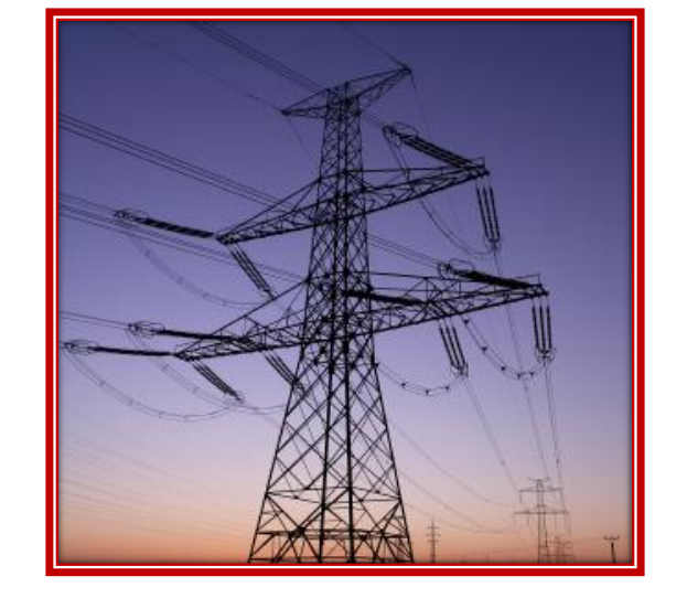
AC is widely used because of its ability to be easily transformed to different voltages using transformers. This makes it ideal for long-distance power transmission. The current and voltage in an AC circuit continuously change with time, reversing direction at regular intervals.
Alternating Voltage and Current
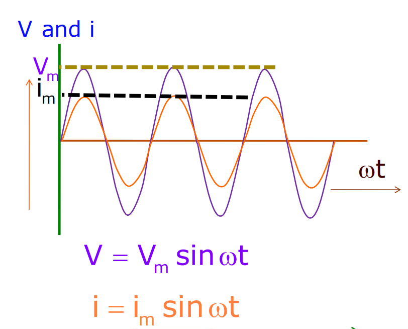
- In AC, the magnitude of alternating current and voltage changes continuously with time, and its direction is reversed periodically.
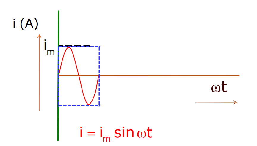
i = iₘ sint
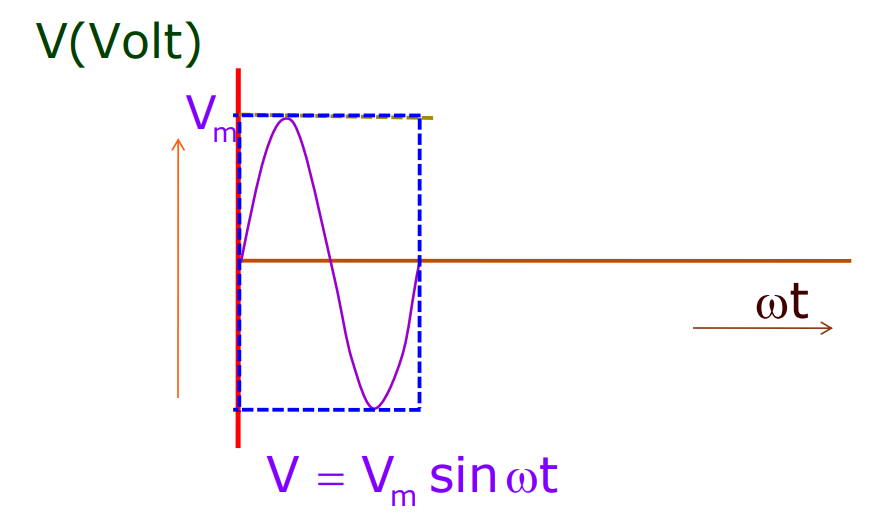
v = vₘ sint
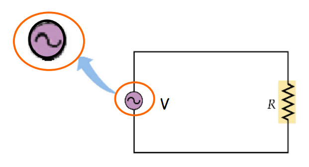
AC Circuit containing Resistance only
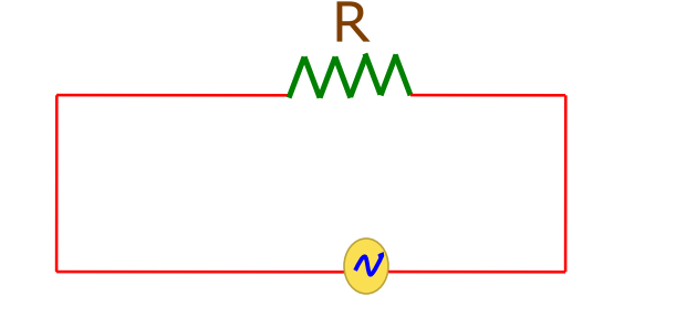
- The instantaneous current in the circuit is
i = iₘ sint (Therefore, i = vₘ /R)
Average Voltage over One Complete Cycle is Zero.
The average Current over One Complete Cycle is Zero.
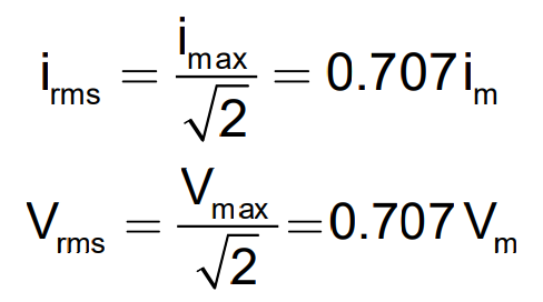
RMS Values of Current and Voltage
Let’s go further in the chapter on alternating current and understand RMS values of current and voltage. When AC flows through a resistor, the current and voltage remain in phase with each other. The maximum or peak values of voltage and current can be described using RMS (Root Mean Square) values, which represent the effective values of AC. The power consumed in purely resistive circuits is given by the product of the RMS values of current and voltage.
Phasors
The chapter alternating current also covers the topic of Phasors. This involves-
- Phasors show a phase relationship between current and voltage.
- In the case of the resistor, alternating current and voltage are in the same phase.
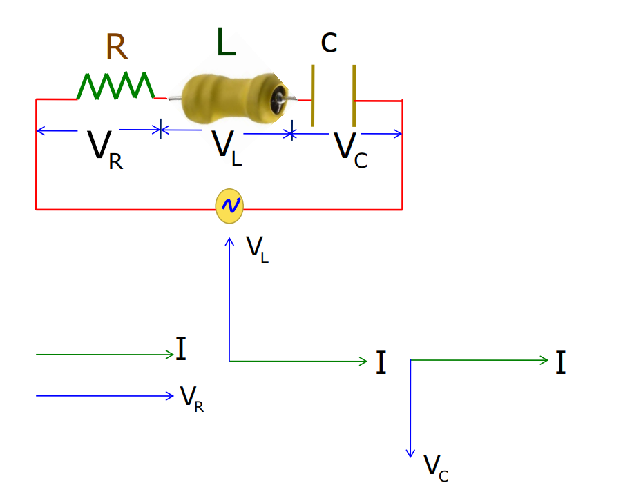
Phasor Diagrams (Resistance Only)
Phasor diagrams from the chapter alternating current visually represent the phase relationships between current and voltage in AC circuits. In purely resistive circuits, the phasors for current and voltage are in phase, while in inductive and capacitive circuits, they differ by 90°.
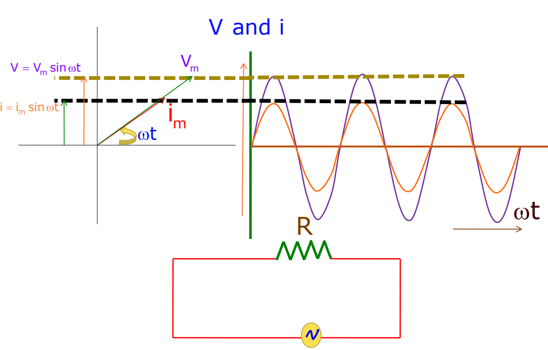
Power Consumed
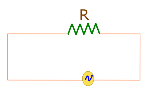
- Instantaneous power dissipated in the resistor
P = i²ₘ R sin²t
- The average power is given by:
Therefore, <P> = 1/2 i²ₘ R
An inductor in an AC Circuit
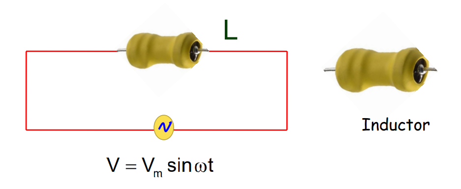
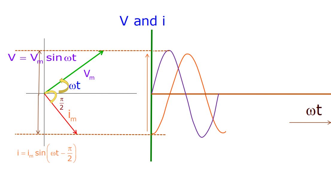
- The instantaneous current is
i = iₘ sin (t – /2) (iₘ = vₘ /L)
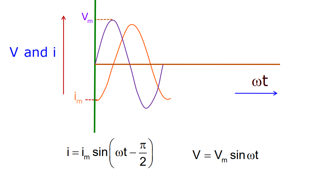
- The current lags the voltage by /2 or one-quarter of the cycle.
Inductive Reactance
- The effective resistance offered by inductance ‘L’ is called inductive reactance
. XL = L
- It has the same dimension as resistance.
- Its S.I. Unit is ohm denoted by.
AC Circuit Containing Inductance Only
 Power Consumed
- The power consumed in an AC circuit with an inductor is given by:
PL = – iₘ vₘ sin2t /2
- The average power consumed by an inductor is zero.
Therefore ( PL) = 0
Capacitor
As stated in the chapter Alternating Current, when AC is applied to a capacitor, we find that.
- The capacitor emits the current but does not completely prevent the flow of charge.
- The capacitor is alternately charged and discharged as the current reverses each half-cycle.
half-cycleitor in an AC Circuit
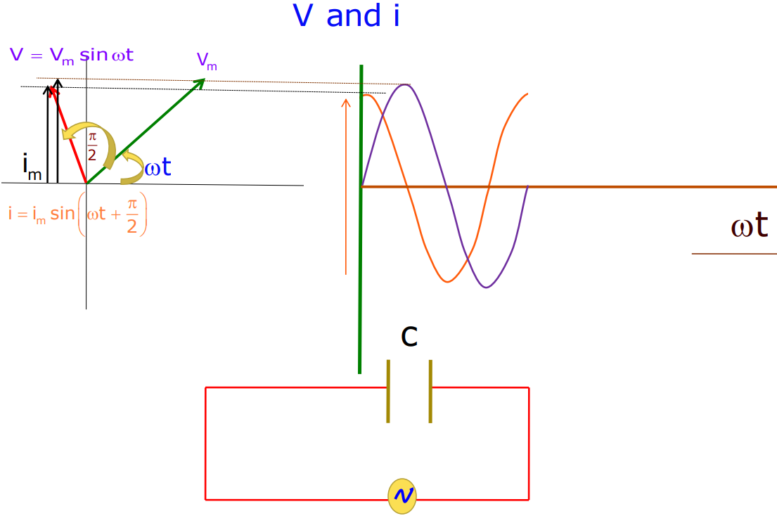
- The instantaneous current that flows through the capacitor is
i = iₘ sin (t + /2) (iₘ = vₘ /1/C)
R = 1/C = Xc (i = v/R)
It is known as the capacitive reactance.
Capacitive Reactance
- The effective resistance offered by capacitance ‘C’ is called capacitive reactance.
Xc = 1/C. It is denoted by Xc.
Phasor Diagram (Capacitor only)
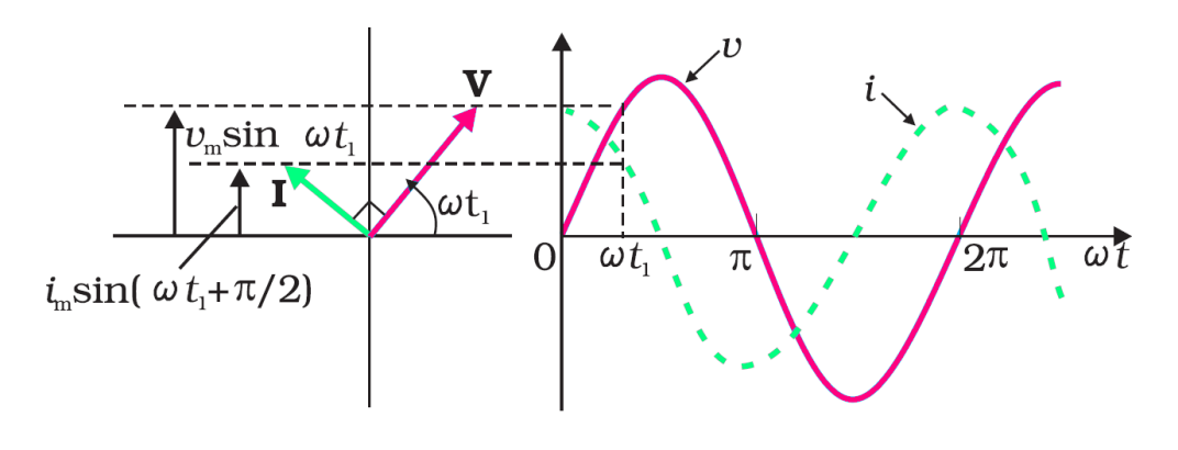
- Current leads voltage by /2.
- Current reaches its maximum value earlier than the voltage by one-fourth of one-fourth
Average Power Consumed
- The instantaneous power supplied to the capacitor is
PC = iₘ vₘ sin2t /2
- Average Power is given by
(PC ) = iₘ vₘ (sin2t /2) = 0. (because sin2t = 0)
- The average power of the AC circuit with a capacitor is zero.
The LCR Circuit

The LCR circuit, which contains a resistor (R), inductor (L), and capacitor (C) in series, is a crucial component in AC studies. The impedance (Z) of the LCR circuit combines the effects of resistance, inductive reactance, and capacitive reactance, determining the overall opposition to AC. Resonance occurs when the inductive and capacitive reactances are equal, leading to a maximum current at a specific frequency called the resonant frequency.
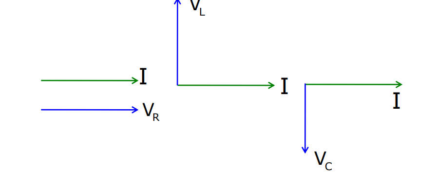
- The voltage across the resistor is in phase with alternating current.
- The voltage across the inductor leads the alternating current by 90⁰.
- The voltage across the capacitor lags the alternating current by 90⁰.
- The current in the RLC circuit is given by:
i = iₘ sin t +
Where iₘ = vₘ/Z and = tan⁻¹ XC – XL/R
Z = √ R² + ( XC – X)²
- The term Z is known as the impedance of the RLC circuit.
Resonance
The chapter on alternating current also covers the concept of Resonance. This covers-
- It occurs in the system, which tends to oscillate at a particular frequency called the natural frequency of the system.
- It occurs in a system driven by an energy source at a frequency that is near the natural frequency of the system.
- Here, the amplitude of oscillation is found to be large.
- Current for RLC circuit, having a voltage of amplitude vₘ.
i = vₘ/Z = vₘ/ √ R² + ( XC – XL)²
- The impedance of the RLC circuit is given by:
Z = √ R² + ( XC – XL)²
Resonant Frequency
- Resonance occurs in the RLC circuit when
XC = XL
- The resonance frequency is, then, given by:
0= 1/√LC
- At a resonant frequency (0), XC = XL
Therefore, Z = R and i = vₘ/R
- Impedance Z is the minimum.
- The current amplitude is maximum.
Sharpness of Renonance
- Amplitude of current (series LCR circuit):
iₘ = vₘ/ √ R² + ( L – 1/C)²
Case 1: when = 0 = 1/√LC
Iₘₐₓ = vₘ/R
Case 2: when is not equal to 0,
iₘ< Iₘₐₓ
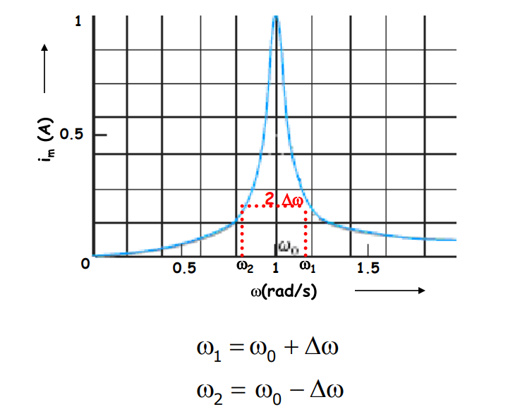
The measure of sharpness of resonance: 0/2
Bandwidth and Q Factor
- Consider two frequencies having:
₁ = 0 +
₂ = 0 –
- The bandwidth of the RLC circuit is given by:
₁ – ₂ = 2
- The sharpness of resonance of the RLC circuit is given by:
0/2 = 0L/R = Q
- It is also known as the Q factor.
- The larger the value of Q, the smaller the bandwidth (2) and the sharper the resonance.
Power in AC Circuit
- The instantaneous power supplied by the source in the RLC circuit is given by: P = vₘ iₘ /2 x cos – cos (2t + )
- The average power over a cycle is <P> = vₘ iₘ /2 x cos
- The factor cos is known as the power factor.
Transformer
The class 12 physics chapter 7 – Alternating current thoroughly covers the topic of a Transformer. Let’s unfold that –
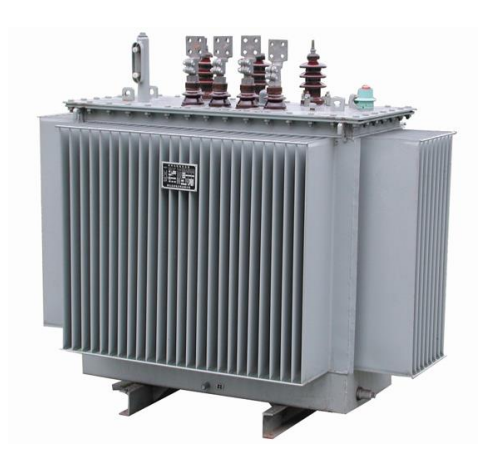
- It is the device that converts low voltage into high voltage and vice versa.
- Transformer consists of two sets of coils: Primary coil (Np turns)- input coil. The secondary coil (Ns turns)- output coil.
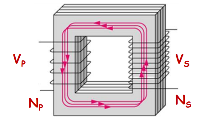
Ideal Transformer
Let’s now see the example of an ideal transformer from class 12 Physics chapter 7 – Alternating Current.
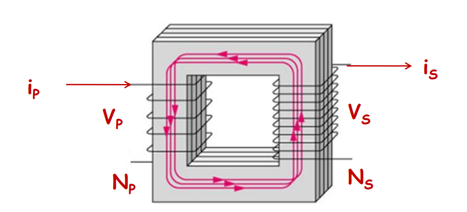
An ideal transformer satisfies:
iP/iS = vS/vP = NS/NP
Step Up Transformer
A transformer which converts low voltage into high voltage.
vS > vP and iS < iP
Step down Transformer
A transformer that converts high voltage into low voltage
vS < vP and iS > iP
Energy Loss in Transformer
The chapter on alternating current also discusses the concept of energy loss in a transformer. This covers-
- Flux Leakage – There is always some flux leakage; that is, not all of the flux due to primary passes through the secondary due to poor design of the core or the air gaps in the core. It can be reduced by winding the primary and secondary coils one over the other.
- Resistance of the Windings -: The wire used for the windings has some resistance and so, energy is lost due to heat produced in the wire (I²R). In high current and low voltage windings, these are minimized by using thick wire.
- Eddy Currents – The alternating magnetic flux induces eddy currents in the iron core and causes heating. The effect is reduced by using a laminated core.
- Hysteresis – The magnetization of the core is repeatedly reversed by the alternating magnetic field. The resulting expenditure of energy in the core appears as heat and is kept to a minimum by using a magnetic material that has a low hysteresis loss.
The large-scale transmission and distribution of electrical energy over long distances is done with the use of transformers. The voltage output of the generator is stepped up (so that the current is reduced and consequently, the I²R loss is cut down). It is then transmitted over long distances to an area sub-station near the consumers. There the voltage is stepped down. It is further stepped down at distributing sub-stations and utility poles before a power supply of 240 V reaches our homes.
Transformers and Energy Transmission
Transformers are devices that convert low voltage to high voltage (step-up) or high voltage to low voltage (step-down) in AC circuits. They consist of primary and secondary coils, and their efficiency is influenced by factors like flux leakage, winding resistance, eddy currents, and hysteresis. Transformers play a vital role in efficiently transmitting electrical energy across long distances.
Let’s Conclude
In conclusion, CBSE Class 12th Physics, Chapter 7 – Alternating Current, provides a comprehensive understanding of the principles governing AC circuits and their applications. From learning about the sinusoidal nature of AC to the in-depth exploration of components like resistors, capacitors, and inductors in AC circuits, this chapter equips students with crucial knowledge for both exams and real-world applications. The significance of resonance in LCR circuits and the role of transformers in energy transmission further solidify the importance of this topic.
By mastering CBSE Class 12th Physics, Chapter 7 – Alternating Current, students can confidently solve problems related to AC circuits and develop a deeper appreciation of electrical systems. The concepts learned here, including the calculation of power, impedance, and the role of the power factor, are essential for understanding modern electrical infrastructure.
Whether preparing for board exams or deepening conceptual knowledge, CBSE Class 12th Physics, Chapter 7 – Alternating Current offers a solid foundation in electrical circuits, making it a critical component of the Class 12th Physics syllabus. At iPrep, we provide extensive resources like videos, practice questions, and notes to help students excel in this chapter and beyond.
Practice questions on Chapter 7 - Alternating Current
Get your free Chapter 7 - Alternating Current practice quiz of 20+ questions & detailed solutions
Practice Now


