Electromagnetic Induction – The Best Guide For Class 12 Physics Chapter 6
Welcome to iPrep, your Learning Super App. Our learning resources for the chapter, Electromagnetic Induction in Physics for Class 12th are designed to ensure that you grasp this concept with clarity and perfection. Whether you’re studying for an upcoming exam or strengthening your concepts, our engaging animated videos, practice questions and notes offer you the best of integrated learning with interesting explanations and examples.
The chapter Electromagnetic Induction explores the fundamental principles behind the generation of electromotive force (emf) and electric currents in conductors exposed to changing magnetic fields. It introduces key concepts like magnetic flux, Faraday’s Law, which states that the induced emf is proportional to the rate of change of magnetic flux, and Lenz’s Law, which explains the opposing direction of induced currents. The chapter also discusses motional emf, eddy currents, and inductance, highlighting their applications in devices such as generators, transformers, and electric motors. This chapter provides essential insights into how electromagnetic induction is harnessed in modern electrical systems and technologies.
Electromagnetic Induction
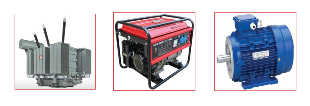
The chapter on Electromagnetic Induction delves into the fascinating world of induced electric currents and magnetic fields, laying the foundation for the operation of many electrical devices we rely on daily, such as power generators, electric motors, and transformers.
Introduction – What is Electromagnetic Induction?
Electromagnetic induction refers to the generation of electric current or electromotive force (emf) in a conductor when exposed to a varying magnetic field. This phenomenon was first discovered by Michael Faraday and Joseph Henry, whose experiments demonstrated that electric currents could be induced when a magnet moves near a coil or when a circuit is exposed to a changing magnetic field.
Faraday and Henry’s Experiments
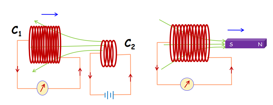
These experiments from the chapter on electromagnetic induction show that whenever there is relative motion between a magnet and a coil or between two coils, an electric current is induced.
Experiment 1:
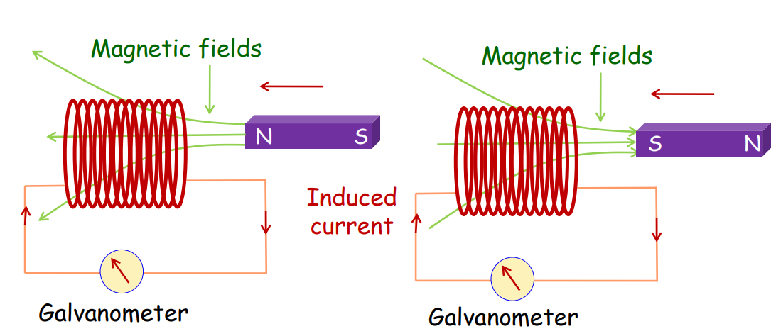
- When a bar magnet is moved towards or away from a coil, current is induced in the coil.
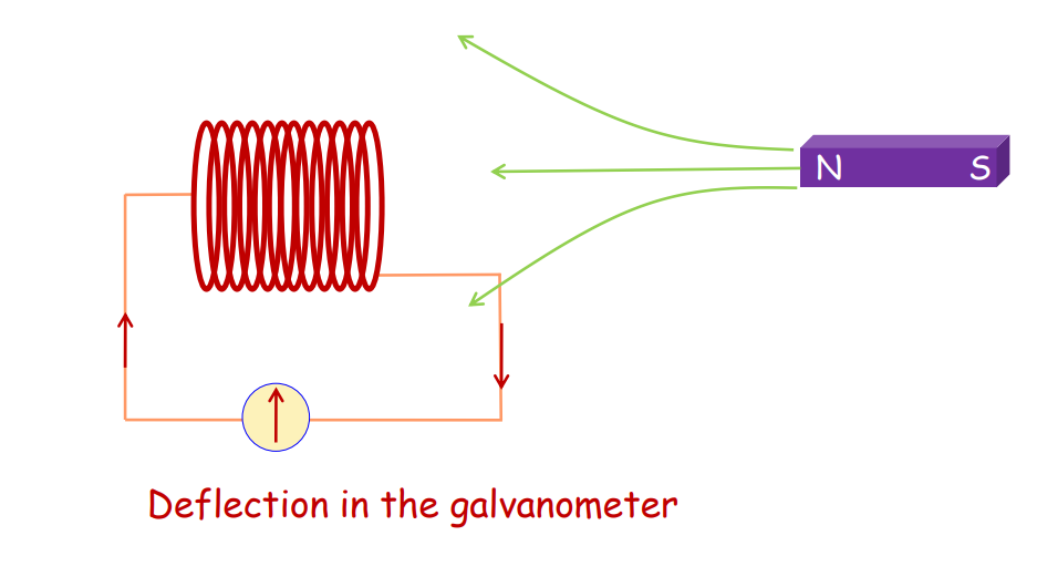
- Whenever there is a relative motion between the magnet and the coil, an electric current is induced and flows through the circuit.
Experiment 2:
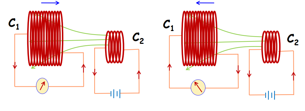
- When a circuit coil is moved towards or away from a current-carrying coil, an electric current is induced in the circuit coil.
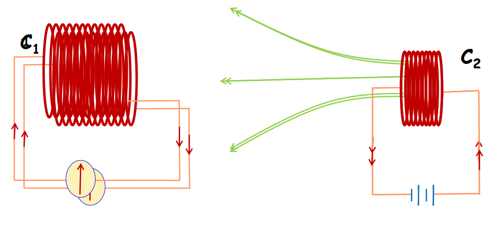
- Whenever there is a relative motion between the coils, an electric current is induced in the coil and flows through the circuit.
Experiment 3:
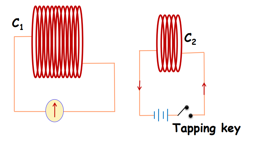
- Current is also induced when there is a varying magnetic field linked with a circuit coil.
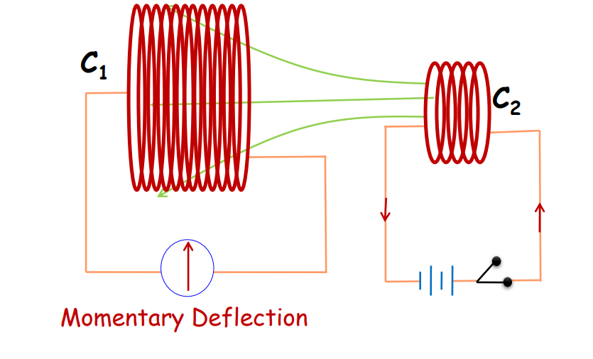
- When the tapping key is pressed, the galvanometer shows a momentary deflection. But the pointer returns to zero immediately.
- There is also a momentary deflection in the galvanometer when the key is released.
Current is induced in the circuit when there is a varying magnetic flux linked with it.
Magnetic Flux
Further in the chapter Electromagnetic Induction, we’ll understand the concept of magnetic flux.
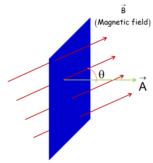
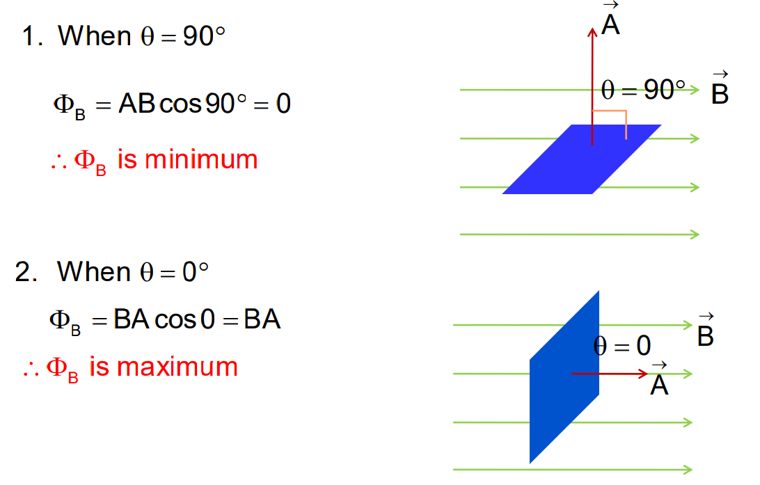
Magnetic flux is the measure of the number of magnetic field lines passing through a surface. It is mathematically expressed as ΦB = BAcosθ, where B is the magnetic field, A is the area, and θ is the angle between the magnetic field and the area. When magnetic flux changes, an induced emf is created.
If we consider a surface in which the magnetic field has different magnitudes and directions, then the total magnetic flux is given by:
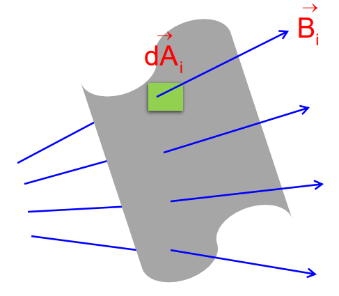
ΦB = B₁ .dA₁ + B₂.dA₂ +………….
Therefore, ΦB = ALLBᵢ .dAᵢ
Faraday’s Law of Electromagnetic Induction
As mentioned in the chapter Electromagnetic Induction, Faraday’s law states that the induced EMF in a circuit is directly proportional to the rate of change of magnetic flux through the circuit.
- It is given by ε = -dΦ/dt, where the negative sign indicates that the e.m.f induced opposes the change in magnetic flux associated with the circuit.
- The induced e.m.f in the case of a closely wound coil of N turns is given by:
ε = -NdΦ/dt
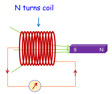
- Induced e.m.f can be increased by increasing the number of turns of the coil.
Lenz’s Law and Conservation of Energy
The chapter Electromagnetic Induction further covers Lenz’s law of conservation of energy. This involves-
- The polarity of induced e.m.f is such that it tends to produce a current that opposes the change in the magnetic flux that produced it.
- The law gives the direction of the induced e.m.f in the circuit.
- It is by the law of conservation of energy.
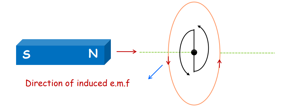
- When the north pole of the bar magnet moves towards the coil, the induced current in the coil will be anti-clockwise.
- The end of the coil nearer to the north pole will become north and the induced current will be anti-clockwise.
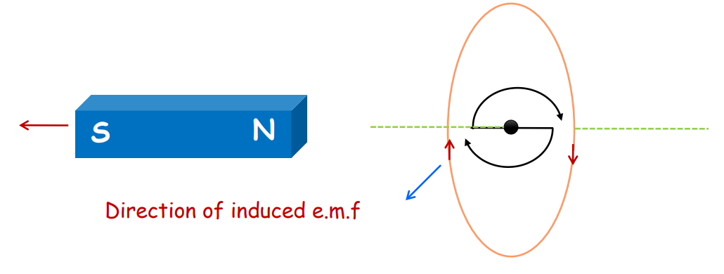
- When the north pole of the bar magnet moves away from the coil, the induced current in the coil will be clockwise.
- When the north pole of the bar magnet moves away from the coil, the induced current will be in the clockwise direction.
Motional Electromotive Force
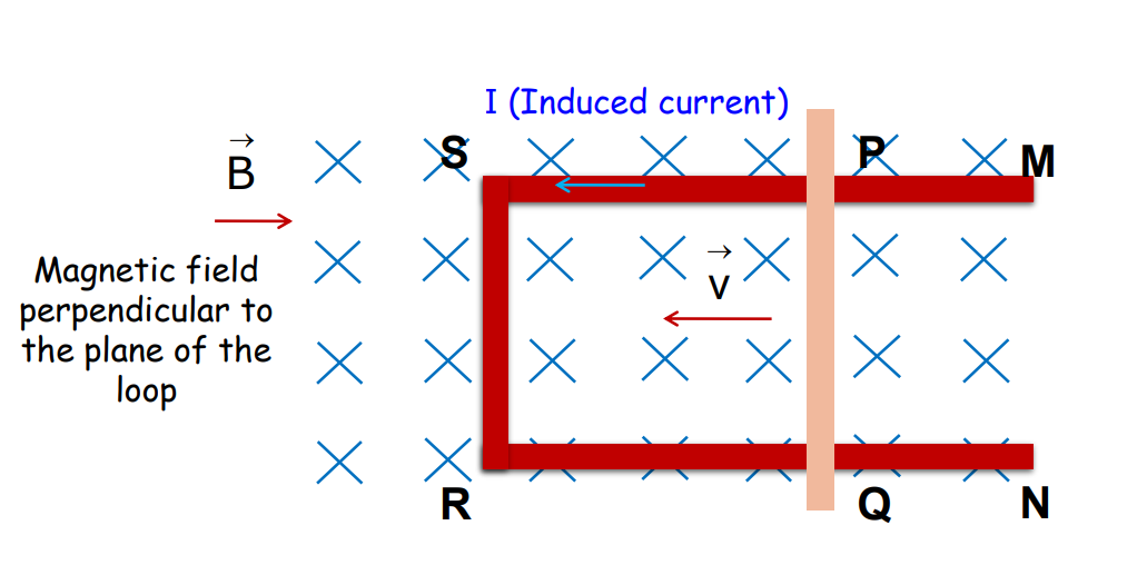
When a conductor moves through a uniform magnetic field, a motional emf is induced. The magnitude of this emf is given by ε = Blv, where B is the magnetic field strength, v is the velocity of the conductor, and l is the length of the conductor.
Expression for Motional EMF using Lorentz Equation
The magnitude of the Lorentz force, acting on the free-charged carriers of the conductor PQ is given by:
F = qvB
Since all the charged carriers experience the same force, in magnitude and direction, the work done in moving from P to Q is given by:
W = Fl = qvBl
The e.m.f induced is the work done per unit charge
Ε = W/q = qvBl/q = vBl
It is the same as derived using Faraday’s law.
Lenz’s Law: Conversation of Energy
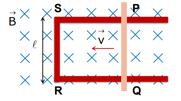
- The power required to push the arm PQ of the loop PQRS with a constant velocity v in a uniform magnetic field B is
P = B²l²v²/r, where r is the resistance of the arm PQ.
- On the other hand, the heat dissipated per unit time in the current flowing loop is given by: P = I²r = B²l²v²/r.
It is the same as the power required to push the arm PQ.
- The mechanical energy needed to move the arm PQ is converted into electrical energy that flows through the loop.
- The electrical energy is again dissipated as heat energy from the current carrying loop.
- Therefore, Lenz’s law is the law of conservation of energy
Inductance
As discussed in the chapter electromagnetic Induction, Inductance is the property of a conductor by which a change in current induces an emf either in the same conductor (self-inductance) or in a nearby conductor (mutual inductance).
The inductance of a coil is directly proportional to the number of turns in the coil and the rate of change of magnetic flux.
NΦB ∝ I
where, ΦB: Magnetic flux, B: Induced current, and N: no of turns of the coil.
Therefore, NΦB = K I
The constant of proportionality K is termed inductance.
Self – Inductance
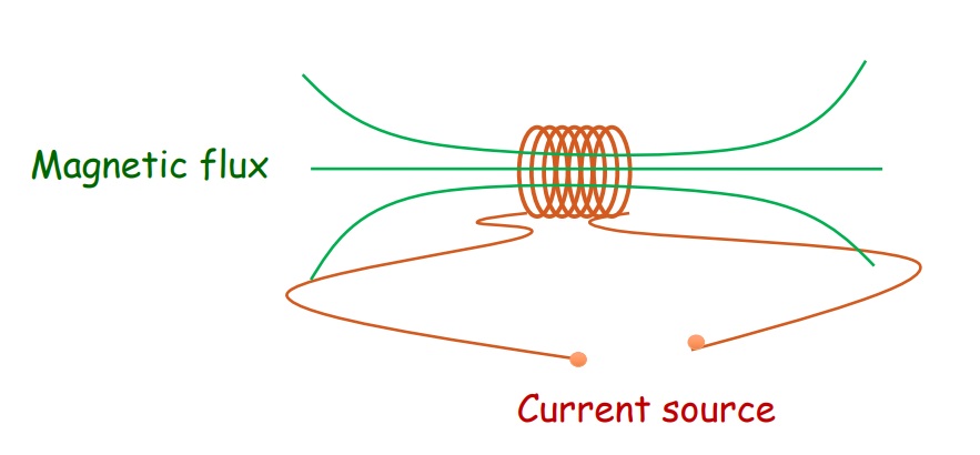
- Whenever the electric current passing through the coil changes, magnetic flux linked with the same coil changes, and an e.m.f is induced in the coil.
- This phenomenon is known as Self-Inductance.
- The magnetic flux linkage through the coil of N turns is directly proportional to the current through the coil.
NΦ ∝ I
Therefore, NΦB = L I
- Where L is known as the self-inductance of the coil or the coefficient of self-induction of the coil.
- SI unit of L is Henry (H).
- When the current through the coil changes, the flux linked with the coil also changes and an e.m.f. is induced in the coil.
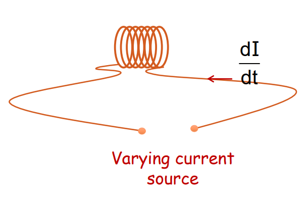
Therefore, ε = – L dI/dt
- The induced e.m.f. Always opposes any change of current in the coil.
Self – Inductance of a Long Solenoid
The self-conductance of a long solenoid of cross-sectional area A and length is given by:
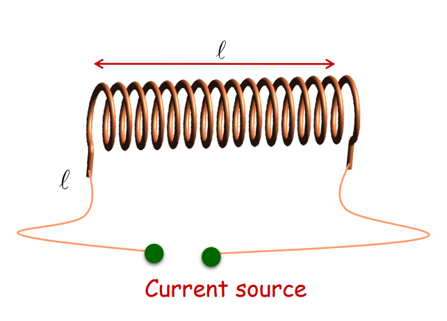
L = ₀n²lA
Where n is the number of turns per unit length of the solenoid.
Material having relative permeability ᵣ
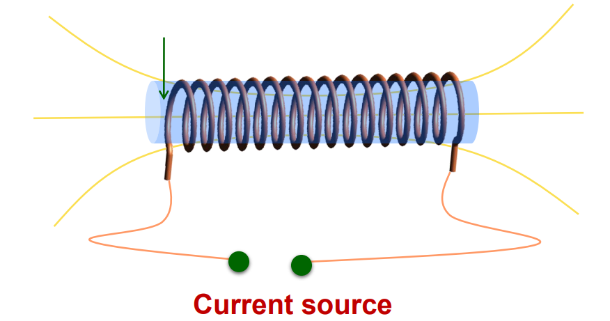
If the material of relative permeability(ᵣ) is inserted between the solenoid, then.
L = ᵣ₀n²Al
Energy stored in an Inductor
Going further in the chapter Electromagnetic Induction we’ll discuss about the energy stored in an inductor.
- When current flows through an inductor, energy is stored in the form of magnetic potential energy.
- The magnitude of the magnetic energy is given by:
W = 1/2LI²
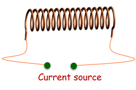
Where L is the inductance of the coil and I is the current flowing through the inductor.
Analogy of Inductance and Mass
Let us now understand the analogy of inductance of mass from the chapter Electromagnetic Induction.
- Inductance (L) is analogous to mass (m).
- In an electrical circuit that consists of inductors, L acts as the electrical inertia as mass does in mechanics.
- Inductance opposes the growth and decay of current in the electrical circuit.
Mutual Inductance
The chapter Electromagnetic Induction also covers the concept of Mutual Inductance. This covers-
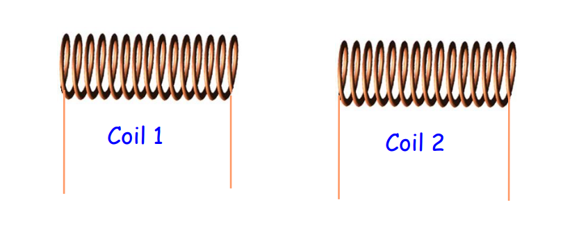
Whenever the current passing through the coil changes, magnetic flux with the neighboring coil changes, and e.m.f is induced in the neighboring coil. This phenomenon is called mutual inductance.
Mutual Inductance of Two Long Co-axial Solenoids
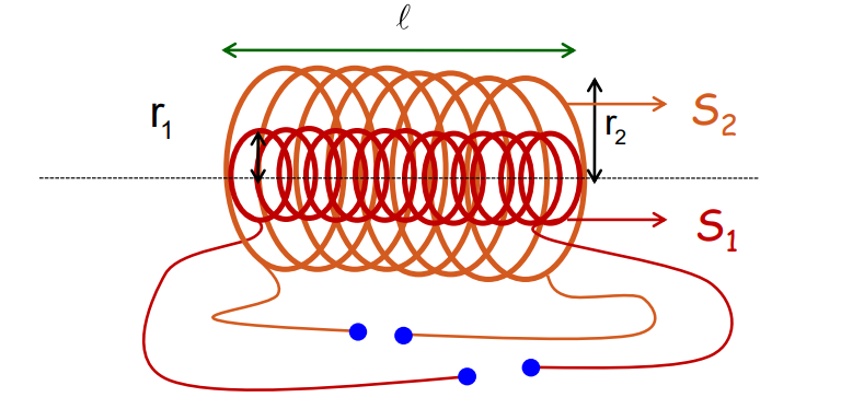
The mutual inductance of the two coils is given by:
M = ₀n₁n₂r²₁l
This relation holds good as long as the length of the solenoids is long and
l >>r₁ or r₂
In a medium of relative permeability(ᵣ), the mutual inductance between the coils is given by:
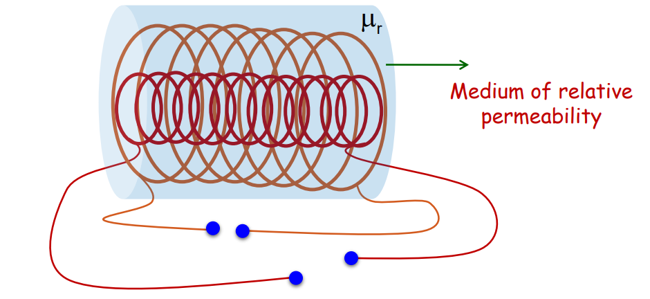
M = ᵣ₀n₁n₂r²₁l
Induced e.m.f. When Currents are Flowing through both the Coils
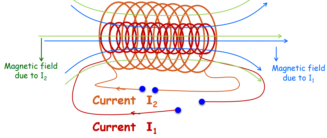
The induced e.m.f in the inner coil is given by:
ε = – M dI₂/dt – L dI₁/dt
AC Generator
Going further in the chapter Electromagnetic Induction, we’ll also understand the basics of AC Generator.
- An electrical device that converts mechanical energy into electrical energy.
- It works on the principle of electromagnetic induction.

Constructions
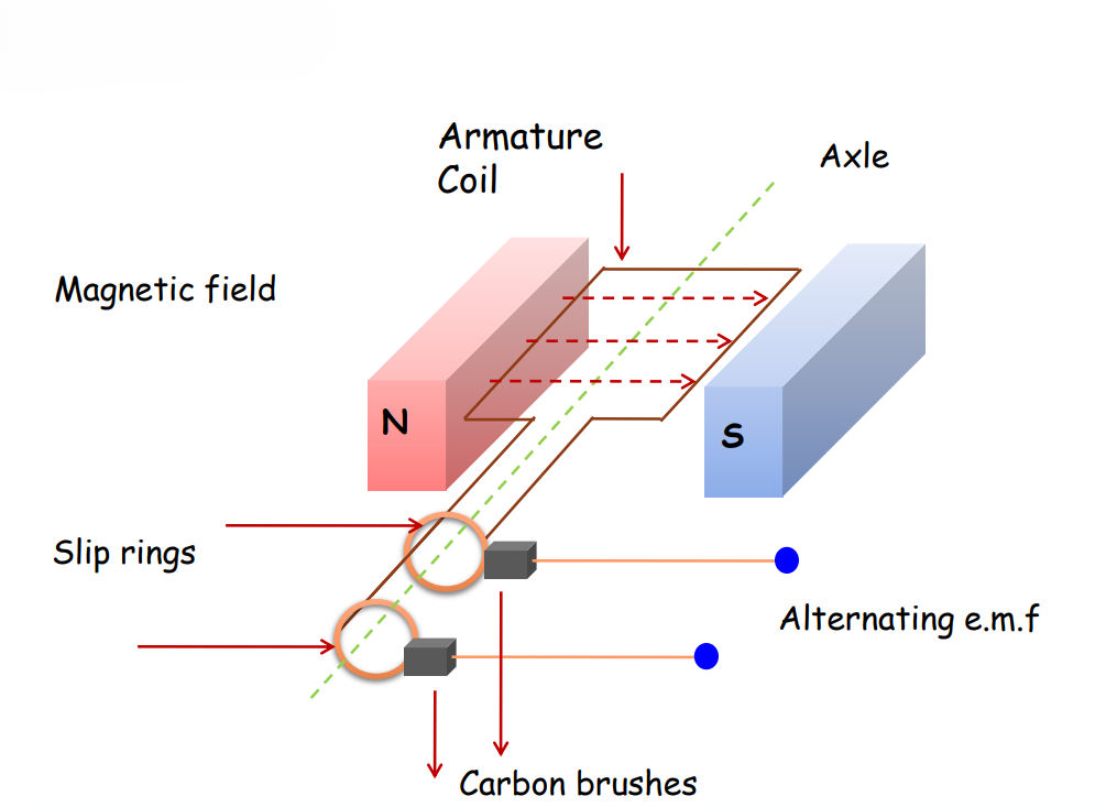
Whenever a closed coil is rotated in a uniform magnetic field about its axis perpendicular to the field, the magnetic flux linked with the coil changes which results in induced eAcrossacross its ends.

Working:
- The armature is rotated mechanically in a uniform magnetic field by some external agency.
- Due to the on of the coil, magnetic flux changes. This induces the e.m.f in the coil.
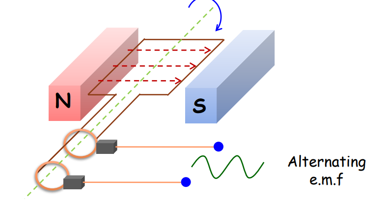
- The induced e.m.f. in the coil is
ε = ε₀sint (because ε₀ = NBA )
- The direction and magnitude of the induced current changes periodically. Therefore, the current obtained is the alternating current.
Applications of AC Generator
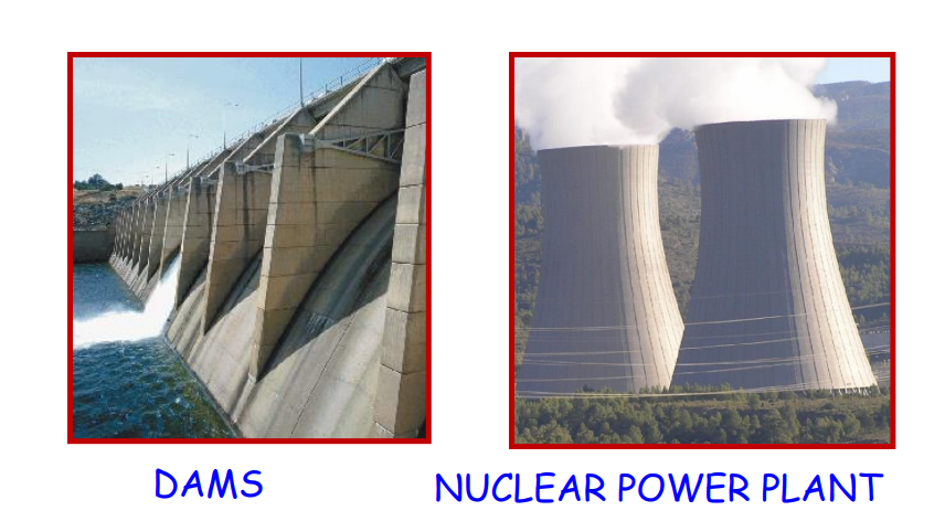
They are used in commercial generators, dams, thermal plants, and nuclear reactors.
Let’s Conclude
In conclusion, CBSE Class 12th Physics, Chapter 6 – Electromagnetic Induction offers a comprehensive understanding of how electric currents are induced by changing magnetic fields, forming the backbone of many electrical systems. This chapter covers critical concepts such as magnetic flux, Faraday’s Law, and Lenz’s Law, each vital for understanding the principles behind devices like generators, transformers, and electric motors.
By mastering the concepts in Electromagnetic Induction from Class 12th Physics, students will gain a deeper insight into modern electrical technologies and applications. The chapter also introduces key ideas like motional emf and inductance, which have wide-reaching implications in both academic learning and practical applications. With iPrep’s resources, including engaging videos and practice questions, students can confidently navigate the complexities of Electromagnetic Induction in Class 12th Physics.
To read the NCERT text of Class 12 Physics Chapter 6 Electromagnetic Induction, click here.
Practice questions on Chapter 6 - Electromagnetic Induction
Get your free Chapter 6 - Electromagnetic Induction practice quiz of 20+ questions & detailed solutions
Practice Now


